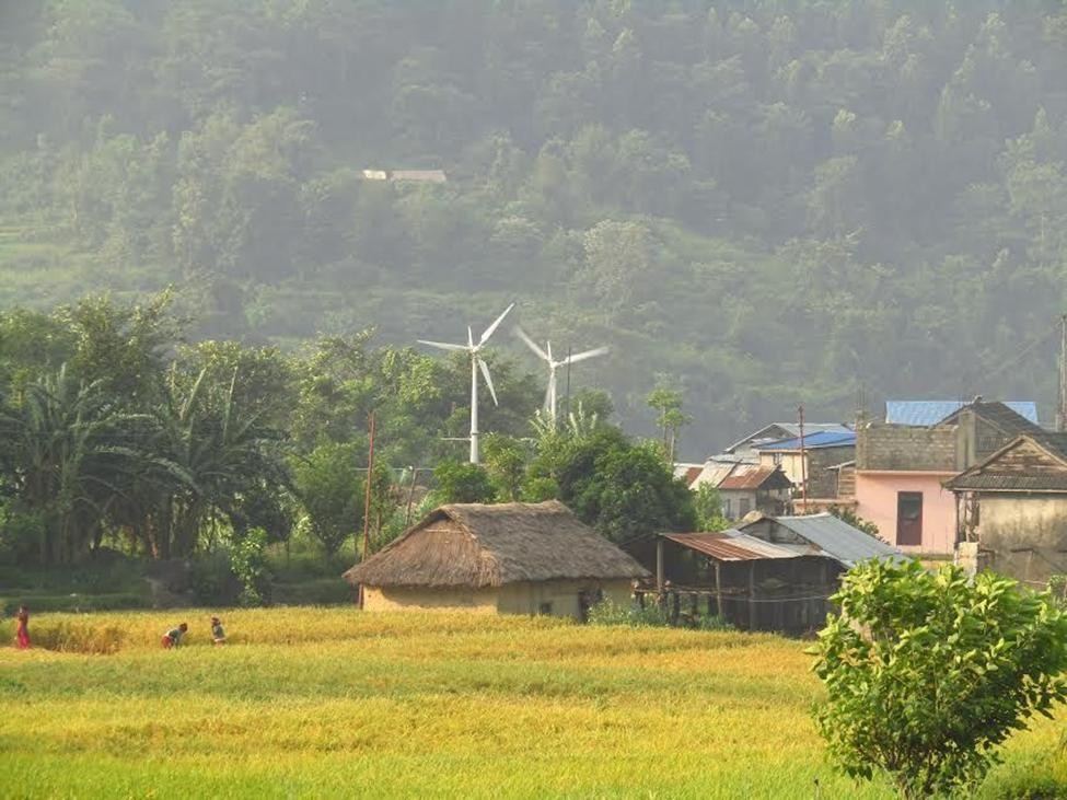
A wind turbine is a device designed to utilize the kinetic energy of wind and convert it to electrical energy. A typical wind turbine starts generating electricity when the wind speed is 2-4 m/s, otherwise known as cut-in wind speed and achieves its maximum output power at rated wind speed which is generally 12-17 m/s. The maximum output power of a wind turbine is also termed as Rated Output Power. As the wind speed goes on increasing, the forces acting on the turbine increase simultaneously. The increasing forces on the turbine are hazardous to the turbine structure. Therefore at certain speed, the turbine is brought to standstill, this speed is known as cut-out wind speed. Beyond the cut-out wind speed, a turbine is designed to withstand speedy wind conditions which range higher than cut-out wind speed. This ultimate wind speed which a turbine can withstand safely is known as survival wind speed.[Note: The above graph shows how the power output varies accordingly with the rise in wind speed and remains uniform throughout a certain speed limit. The graph is a general representation of behavior of a wind turbine with the varying wind condition. It should not be used as reference for factual data.]
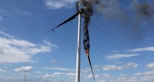
Therefore, for the purpose of safe operation of wind turbines under extreme wind conditions and increasing their life span certain mechanisms are deployed in order to protect the turbines from going to breakdown which we shall refer to as Over Speed Protection Mechanisms.However, these mechanisms are not solely deployed to for their protection. One of the main purposes of such mechanisms is also to harness the maximum power from the available wind energy at the moment. Some of the prominent Over Speed Protection Mechanisms are briefly explained below.
- Furling Mechanism
Furling is another method used for safety of the wind turbines as well as for optimum power regulation. In this mechanism, the blades are turned away from the wind if the wind speed crosses the safety limit of the system. Unlike pitching, where individual blade angles are monitored and controlled, furling allows the whole set of blades to change its position as per the speed and direction of the wind. Furling can also be of two types, viz. Horizontal Furling and Vertical Furling, depending upon the curvature of movement of the rotor.
- Yawing Mechanism
Yawing mechanism is used for the precise positioning of the nacelle in the wind. A nacelle is the casing in which component like gear box, generator and braking components are enclosed. The yaw system enables the nacelle to be optimally positioned in the wind allowing it to be readjusted if the permitted deviation between the wind direction and nacelle is exceeded. Most of the small wind turbines use tail vane for the purpose of positioning but in case of large wind turbines the nacelle movement is usually monitored by computer and electronic. An anemometer is attached at the top end of the nacelle which detects the speed and the direction of the wind at that moment.
- Braking System
Generally there are two types of braking systems used in wind turbines. The first is Mechanical Braking System where the whole rotor is brought to standstill in case of extreme wind conditions, emergencies and maintenance purposes. The mechanical brake constitutes of a circular disc attached to the rotor shaft. So, when braking has to be done, the brake shoe mounted on the brake disc clamps the disc and hence stops the motion of the motor.
The second is Aerodynamic Braking System. Apart from mechanical braking which brings about a complete stoppage to the rotor, aerodynamic braking system decreases the speed of the rotor and keeps the turbines running power production. This is done generally by adjusting the rotor blades along their longitudinal axis as required by the wind conditions. Aerodynamic braking is generally spring operated which is further monitored by computer and electronic devices.Depending upon the cost and manufacturing differences, hydraulic braking is also used which is nothing but the use of hydraulic fluids for amplifying the braking forces.
- Pitch Control Mechanism
Pitching in simple terms is the adjustment of blade angles of wind turbine blades in order to harness optimum power from wind or to protect the turbine from unexpected forces and power output caused by high speed wind. An advanced pitch control mechanism allows the rotor blades’ angle of attack to be measured, monitored and controlled. With the help of such features the rotor blades’ angle can be adjusted continuously so as to capture optimum wind energy and the rotor blades can be automatically turned off if required. Basically, there are two major types of pitch control mechanisms which are briefly described below.
- Active Pitch Control
In active pitch control mechanism, the rotor blades turn around their longitudinal axis by a computer controlled mechanism. This type of control mechanism requires advanced technologies which combine principles of mechanical, electronics and cybernetics.
- Passive Pitch Control
In passive or stall pitch control mechanism, contrary to active pitch control, the rotor blades do not rotate around their longitudinal axis. Instead, the rotor blades are aerodynamically designed to create a stall and lower the rotation speed under high speed wind conditions. These types of rotor blades require precise blade design and strong towers.
[Note: Pitch control mechanism is only required in Horizontal Axis Wind Turbines (HAWT). Vertical Axis Wind Turbines (VAWT) are always under the influence of optimal wind speeds.]